I recently had to design a 2 active stage amplifier for a class. So, I turned to my favorite OpAmp, the TPA6120 (check out my older post for more info about this IC). The datasheet for this IC recommends using it in conjunction with the Burr Brown OPA134, another fantastic little OpAmp. Though not quite as fast as the mighty TPA6120, the OPA134 has a very respectable 8 MHz bandwidth and 0.00008% THD.
BTW: Given the difficult to mount SO-20 PowerPad package TI uses for the TPA6120, I now offer a breakout board at AstrusLabs.com.
For this project, I took what I had leaned from my implementation of the C-Moy amplifier design, and designed a new circuit with the same four stages as before:
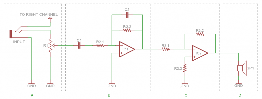
Figure 1: Left Channel Amplifier Circuit
(A) Input Stage
A potentiometer (or pot for short), R1, is used as a voltage divider to control the volume on the input side. The pot is chosen based on resistance and number of turns. The resistance of the pot should be significantly higher than the output impedance of the source (i.e. the MP3 player plugged into the amp). The number of turns determines the resolution, a 10 turn 1kΩ will allow for more sensitive fine tuning than a single turn 1kΩ pot. I used a pair of 50kΩ single turn pots this time which seem to work well (I usually just try whatever I have on hand for this part and see what works).
(B) Filter Stage
The filter stage serves to protect the amp and headphones from a DC biased input, and prevents high frequency noise from making it’s way into the circuit. Unlike the stock CMoy design’s passive low-pass filter, this circuit uses the OPA134 (IC1) in an inverting active band-pass filter configuration; calibrated to filter out signals below 10 Hz, as well as signals above 60 kHz. The range of human hearing is about 20 Hz to 20 kHz, so this easily encompasses that with some extra padding.
To define the two cutoff frequencies (fc), the below equation is used twice:

Once using R2.1 and C1, for the low frequency cutoff, and once using R2.2 and C2 for the high frequency cutoff. I chose to use 1kΩ resistors for both and derived the capacitor values from there. It is notable to mention that using two different resistors will result in an application other than unity gain at this stage, so it’s best to choose the resistors first.
(C) Amplifier Stage
The amplifier stage is simply an inverting OpAmp configuration using the TPA6120 (IC2). Owing to the TPA6120’s relatively low input impedance, developing an unwanted DC bias across the input pins has been known to be a common issue when implementing this IC. To address this, normally one would attempt to balance the path to ground resistance from each input. In this case a third resistor, R3.3, can be used to balance the path-to-ground resistance on the input pins. Because the OPA134 is in the path, calculation of this value is more difficult. To determine the correct value for R3.3, I installed a 50kΩ potentiometer, and adjusted it while monitoring the circuit with an oscilloscope. I should mention that simply grounding the non-inverting pin only results in 60mV offset, so the consequences aren’t quite as drastic as in the previous amplifier.
It may be tempting to address the issue of DC-bias with a decoupling capacitor on the front end; however, the TPA6120 datasheet specifically recommends against this solution, since it may produce undesired oscillations on the output signal. The datasheet also offers a lot of other good design considerations, and I do recommend reading it over before modifying or designing your own amplifier.
(D) The Driven Load
This portion of the circuit represents the impedance of the speakers being driven. In my case this would be the impedance of one side of a pair of AKG K-240 Studio headphones, or 55Ω.
Other Considerations
The TPA6120 is a very finicky IC, and requires very clean power. It is necessary to use decoupling capacitors (preferably low ESR, though I’ve had good results with electrolytics too) .
 A 2-Stage Headphone Amp Using the TPA6120 and OPA134 Blog Post by Cheesed-Off.com is licensed under a Creative Commons Attribution-ShareAlike 3.0 Unported License.