I really wished this information was more readily available when I built my amplifier circuit, which is the reason I’m writing this. After purchasing a pair of AKG K-240 Studio Headphones, I decided I wanted a headphone amp to help drive them, and decided to build one, more or less, for the educational value. Having built electronics kits in the past, I really didn’t want to just assemble a pre-existing kit. After reading about various OpAmps, I settled on the TPA6120. This IC operates between 5V and 15V, a fine range to power with 9V batteries. It also has a very fast slew rate 1300V/μs, low noise, and a low THD rating.
Update: Given the difficult to mount SO-20 PowerPad package TI uses for the TPA6120, I now offer a breakout board at AstrusLabs.com.
I should mention before continuing, this information applies to headphone amp design, and I cannot comment on it’s compatibility with other applications (such as guitar or microphone preamps). If you’re interested in driving something other than headphones, I suggest you look into the specific design considerations for your application.
As a starting point, I referenced the four stage C-Moy amplifier design:
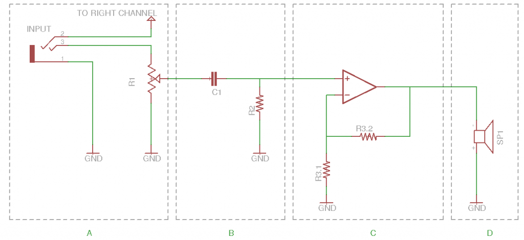
Figure 1: Left Channel Amplifier Circuit
(A) Input Stage
A potentiometer (or pot for short), R1, is used as a voltage divider to control the volume on the input side. The pot is chosen based on resistance and number of turns. The resistance of the pot should be significantly higher than the output impedance of the source (i.e. the MP3 player plugged into the amp). The number of turns determines the resolution, a 10 turn 1kΩ will allow for more sensitive fine tuning than a single turn 1kΩ pot.
I used a pair of 2.2kΩ single turn trim-pots I pulled from an old Behringer Amp; which seem to work well for me, but may or may not fit your needs.
(B) Filter Stage
The filter stage serves to protect the amp and headphones from a DC biased input. The job of the capacitor (C1) is to block DC, and the job of the resistor (R2) is to set a predictable high pass cutoff frequency. Together these two components function as a highpass filter. The cutoff frequency should be below 20Hz (the lower extent of human hearing), and is found using the equation:

where fc is the cutoff frequency, R is the resistance of R2 in Ohms, and C is the capacitance of C1 on Farads.
For reasons I will explain later, I chose values of 175Ω and 220μF for R2 and C1, resulting in a cutoff frequency of approximately 7Hz, well below the 20Hz limit.
(C) Amplifier Stage
The amplifier stage is simply a non-inverting OpAmp configuration. There is a lot of information available elsewhere that would do a far better job than I could, explaining how this amplifier configuration works. The important thing here is the gain equation:
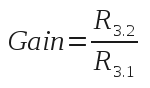
This determines how much larger (or smaller) the output is compared to the input. Since the TPA6120 datasheet recommends a value of 1kΩ for the feedback resistor: I chose resistance values of 240Ω and 1kΩ for R3.1 and R3.2, respectively; resulting in a gain of approximately 5.
Since the TPA6120 has a relatively low input impedance for an OpAmp, balancing the apparent impedance at the input is crucial to prevent a DC bias from forming at the output. This simply means that the resistance between each input pin and ground should be close to the same value. For this amplifier circuit, it means the resistances of R2, R3.1, and R3.2 are all related by the following equation:
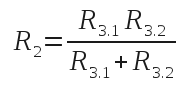
This relationship (along with the availability of parts in my collection) is why a resistance of 175Ω was chosen for the filter stage; the capacitance was chosen based on what I had on hand.
It may be tempting to address this issue by adding a decoupling capacitor on the front end; however, the TPA6120 datasheet specifically recommends against this solution, since it may produce undesired oscillations on the output signal. The datasheet also offers a lot of other good design considerations, and I do recommend reading it over before modifying or designing your own amplifier.
(D) The Driven Load
This portion of the circuit represents the impedance of the speakers being driven. In my case this would be the impedance of one side of a pair of AKG K-240 Studio headphones, or 55Ω.
Other Considerations
While batteries do supply very clean power, I still found it necessary to use decoupling capacitors on the power pins to eliminate noise. As an added precaution I also wound the battery clip leads into twisted pairs to further cut down on RF interference.
![]()
Designing a Headphone Amp Around the TPA6120A2 Blog Post by Cheesed-Off.com is licensed under a Creative Commons Attribution-ShareAlike 3.0 Unported License.
Pingback: A 2-Stage Headphone Amp Using the TPA6120 and OPA134 | Cheesed Off!